The Carburetor Shop LLC
204 East 15th
Street Eldon, Missouri 65026 Home | History | F.A.Q. | Orders | Contact Us | SELL TO US Carburetors | Repair Kits | Other Parts | Literature | Tools | Articles | Troubleshooting | Carburetor Identification Passenger Kits | Truck Kits | Tractor Kits | Industrial Kits | Marine Kits | Multi-carb set-ups Car Comics | Car Records | Car Trading Cards | Subscription Cards | Oakland and Pontiac STROMBERG type SF updraft carburetors
General information | SF | SFM | Sizes | Auto choke | Drip tube | Adjustments General Information The information in this article has been assembled from research of original Stromberg documents of which I am the current caretaker, and my own experience of 50 years working with carburetors. The information may be copied, downloaded, printed, etc. at the discretion of the reader; but should not be sold. We ask only that copies should mention The Carburetor Shop as the source. The universal versions make excellent replacement carburetors to replace other updraft carburetors of lesser engineering or those that do not adapt readily to modern fuel, or those which are simply unobtainable today. SF carburetors The SF series of Stromberg carburetors was the latest major Stromberg updraft design, and could be used for all classes of work, including heavy duty. The SF series were introduced in 1932, and production was continued through 1968. All SF series carburetor took advantage of the then exclusive Stromberg double venturi design that gave increased air velocity at the main discharge jet at all engine speeds to improve fuel atomization. Also available were vacuum accelerator pumps and power circuits, however many carburetors designed for fixed RPM engines eliminated these features for reduced initial costs. All carburetors were equipped with adjustable idle mixture. Most O.E. (original equipment) carburetors were equipped with fixed main metering jets, although some O.E. carburetors and universal carburetors were equipped with adjustable main metering jets. The vacuum accelerator pump activated the power circuit, when engine vacuum fell below a preset level. SFM carburetors The SFM series of Stromberg carburetors were basically standard variations of the SF series with features desired for marine use. These included special rust treating for iron-bodied carburetors, with all jets and moving parts constructed from bronze or naval brass. Brass bodies were also available, primarily used for salt-water applications. Another available feature for the SFM series was an air intake with an upturn rather than the normal horizontal air intake. Many internal parts (floats, jets, plugs, etc) were interchangeable among SF and SFM series carburetors. A drip-tube was offered as a safety feature on the SFM series and would later be offered on the SF series as well. This feature will be covered later in the article. Sizes Both the SF series and SFM series were available in S.A.E. (Society of Automotive Engineers) standard sizes 1, 2, 3, 4, and 5. Nominal 1-inch carburetor, center to center on mounting bolts 2 3/8, bore size approximately 1 3/16 inch. (Often referred to as size 1). Nominal 1 ¼ inch carburetor,center to center on mounting bolts 2 11/16, bore size approximately 1 7/16 inch. (Often referred to as size 2). Nominal 1 ½ inch carburetor, center to center on mounting bolts 2 15/16, bore size approximately 1 11/16 inch. (Often referred to as size 3). Nominal 1 ¾ inch carburetor, center to center on mounting bolts 3 5/16, bore size 1 15/16 inch. (Often referred to as size 4). Nominal 2 inch carburetor, center to center on mounting bolts 3 9/16 inch, bore size approximately 2 3/16 inch. (Often referred to as size 5). The S.A.E. size would be appended to the series to denote a model – examples SF-1, SFM-1 The S.A.E. size denotes physical size only, and tells the enthusiast nothing about airflow capability. The chart below lists original application displacements and then available venturii in inches by S.A.E. size. SF-1, SFM-1 displacement of 133-260 CID, venturi sizes in inches ¾, 13/16, 7/8, 15/16, and 1. SF-2, SFM-2 displacement of 173-428 CID, venturi sizes in inches 13/16, 7/8, 15/16, 1, 1 1/32, 1 1/16, 1 3/32, 1 1/8, 1 3/16. SF-3, SFM-3 displacement of 242-1188 CID, venturi sizes in inches 1, 1 1/16, 1 1/8, 1 3/16, 1 ¼, 1 5/16, 1 3/8, 1 7/16. SF-4, SFM-4 displacement of 318-1503 CID, venturi sizes in inches 1 ¼, 1 5/16, 1 3/8, 1 7/16, 1 ½, 1 9/16, 1 5/8. SF-5, SFM-5 displacement of 471-1698 CID, venturi sizes in inches 1 3/8, 1 7/16, 1 ½, 1 9/16, 1 5/8, 1 11/16, 1 ¾, 1 13/16. CFM Stromberg did not publish CFM ratings; rather, Stromberg published a chart of engine displacements, and the recommended S.A.E. size carburetor and corresponding venturi. However, Stromberg's sister company Zenith DID publish a very few CFM ratings for their 63 series carburetors. The 63 series are VERY similar to the SF series, so I am including this information. Zenith size 2 with 15/16 inch venturi - 111 CFM Zenith size 2 with 1 1/16 inch venturi - 132 CFM Zenith size 3 with 1 1/16 inch venturi - 139 CFM Zenith size 3 with 1 3/16 inch venturi - 177 CFM Zenith size 4 with 1 5/16 inch venturi - 207 CFM Zenith size 4 with 1 1/2 inch venturi - 250 CFM Zenith size 5 with 1 1/2 inch venturi - 256 CFM Zenith size 5 with 1 11/16 inch venturi - 323 CFM
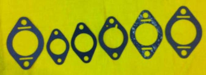
Difficult to judge the relative size of a carburetor from a picture. Therefore the picture below shows the mounting gaskets for the 5 sizes of SF carburetors. The left-most is size 5 and just to the right of it is size 1. From there the sizes increase in order from size 1 to size 5. Note the size 5 gasket is pictured on both ends.
Auto choke The Stromberg documents suggest that auto choke units were available of all sizes of the universal replacement SF series, and S.A.E. size 4 SFM series. A “5” was appended to the end of the model designation to denote the auto choke version, than an auto choke version of an SF-3 became an SF-35. The SFM size 4 with auto choke became an SFM-45. I have yet to see one of the auto choke SF series of any size. Most manual choke butterflies were equipped with a release valve. Drip tube Stromberg machined a boss on the undersize of the air intake on the SFM series carburetors. This boss was threaded for 1/8 pipe thread, and a small orifice was drilled into the air intake in the center of the threaded boss. Another threaded hole tapped for 1/8 pipe was machined ABOVE the throttle plate, and again, a small orifice drilled into the throttle bore. A copper tube could then be connected from the boss on the air intake to the threaded hole above the throttle plate. Why? When an engine with updraft carburetor is turned off, all of the fuel in suspension above the throttle plate drops down (gravity), and could run out the front of the air intake. This was not desirable on marine applications with closed bilges. With the drip tube in place, the fuel would drain into the drip tube, as the orifice was at the lowest point of the air intake, and then would be pulled into the engine when next started. This feature proved so popular that it was made available on the SF series as well as the SFM series carburetors. Adjustments and “gotcha’s” Floats – the floats used in the SF series carbs have a large diameter. To prevent crush, Stromberg inserted a baffle between the two halves of the float. The baffle is LOOSELY held in place by an indented circle in the center of the float. Occasionally, the baffle will be sufficiently loose to rattle when shaking the float. THIS IS OK!!! Test the float by submerging in hot water. If there are no leaks, use it. Do not discard a non-leaky EXPENSIVE float just because of the baffle rattle.
Float settings – there are several different float settings, based on individual application. As a general rule, Stromberg would give FUEL LEVELS at a standard fuel pressure rather than a float setting. If you find a float setting in a reference that looks impossible, check to see if the dimension is for the float setting or the fuel level setting. Fuel pressure – from a 6-inch fuel head (gravity feed) to a MAXIMUM of 2 PSI. The idle mixture screw meters air, not fuel. Thus turning the screw in (clockwise) makes the mixture RICHER!!! A good initial setting is 1 turn from lightly seated. There is an indent in the throttle body where the idle tube is inserted into the throttle body. When rebuilding the carburetor, place the body gasket in place over the lower casting, and then slide the idle tube seal over the portion of the idle tube that protrudes above the body gasket. This seal will then form a seal of the idle tube to the throttle body. Failure to do so will affect idle quality. Adjustable main metering jet (if so equipped) is the more customary turn in (clockwise) lean, turn out (counterclockwise) rich. Use an initial setting of 2 ½ turns from lightly seated. Adjustment range is up to 5 full turns. No increased benefits will be acquired after 5 full turns. The units that were sold for fixed RPM engines that do not incorporate an accelerator pump generally may NOT be machined to incorporate the pump, as the castings are different.
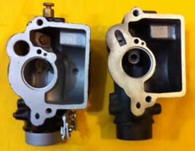
Note in the above picture, the accelerator pump well in the normal bowl on the left, and no provision for machining the accelerator pump well in the economy bowl on the right. |